10101/1/1 Honeywell Fail-Safe Digital Input Module
UBEST – Trusted Global Automation Parts Supplier
We offer a wide range of in-stock industrial automation spare parts. All products come with a 12-month warranty and a 30-day refund for quality issues.
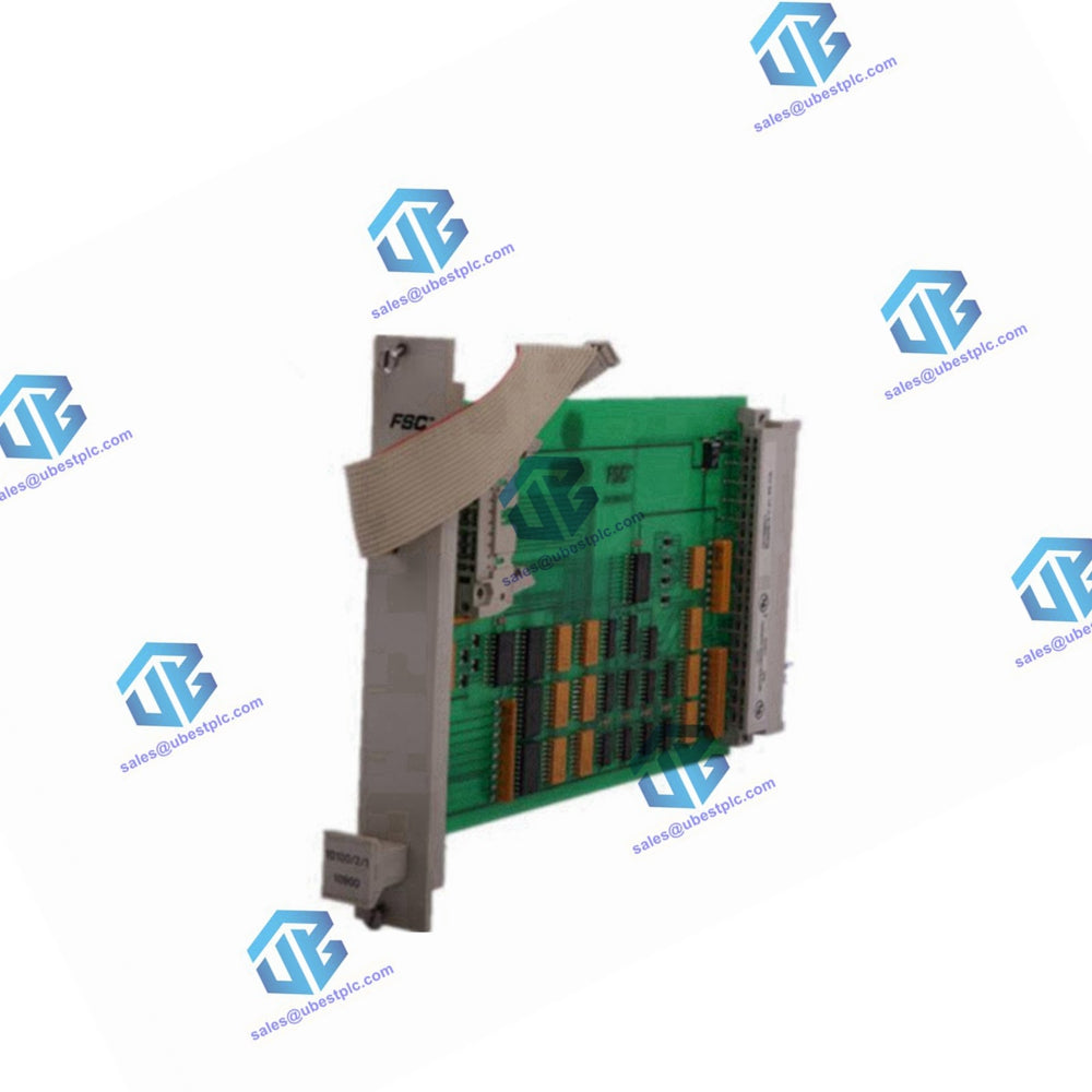
Honeywell 10101/1/1 16-Channel Digital Input Module
Description
The Honeywell 10101/1/1 is a fail-safe digital input module designed to handle sixteen 24 Vdc digital input channels. The module features a 'fail-to-safe' design, ensuring that any component failure results in a de-energized input signal to the processor, thus maintaining safe conditions in a normally energized system. The remaining logic circuitry on the module is thoroughly covered by the system's self-test functions. The supply circuitry is divided into two galvanically isolated groups of eight inputs each, allowing for independent power supply groups and supporting segregation in a process unit or subunit structure.
Technical Specifications
General
- Type Number: 10101/1/1 01703*
- Approvals: CE, TÜV, UL
- Software Versions: All
- Space Requirements: 4 TE, 3 HE (4 HP, 3U)
Power
-
Power Requirements:
- 5 Vdc: 8 mA
- 24 Vdc: 2×100 mA (including input currents)
- Ripple Content (on 5 Vdc): < 0.5 Vp-p (0-360 Hz)
Input
- Number of Input Channels: 16 (2 isolated groups of 8)
- Maximum Input Voltage: 36 Vdc
- Input Current: 7 mA at 24 Vdc
- Input HIGH Voltage: > 15 Vdc
- Input LOW Voltage: < 9 Vdc (I < 2 mA)
- Input Delay: Typically 10 ms
Pin Allocation and Connection Examples
-
Back View and Pin Allocation:
- Pins for 5 Vdc Supply: d2 (GND), z2 (5 Vdc)
- Pins for 24 Vdc Supply (Group 1): d8, z8
- Pins for Input Channels 1-8: d10 (IN 1) to d16 (IN 8)
- Pins for 0 Vdc Supply (Group 1): d18, z18
- Pins for 24 Vdc Supply (Group 2): d22, z22
- Pins for Input Channels 9-16: d24 (IN 9) to d30 (IN 16)
- Pins for 0 Vdc Supply (Group 2): d32, z32
Connection Examples:
-
Non-Redundant I/O Configuration:
- Connect 24 Vdc (internal) power supply to pins z8, z18, z22, and z32.
- Connect input channels as per schematic.
-
Redundant I/O Configuration:
- Ensure both input groups are connected to the 24 Vdc (internal) power supply to prevent fault detection during self-test.