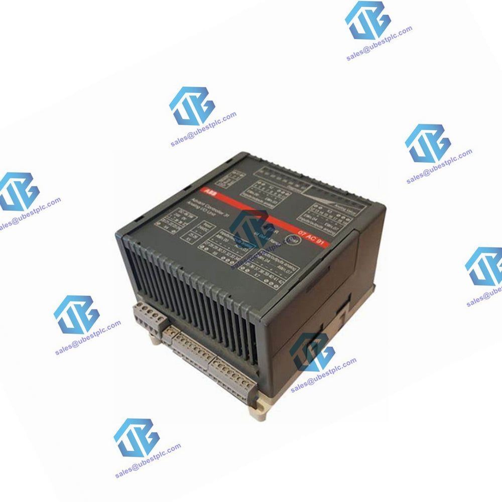
07AI91 GJR5251600R0202 ABB Analog I/O module
Manufacturer:
ABB
Product No.:
07AI91
Condition:
In Stock
Product Type:
Analog I/O module
Product Origin:
Switzerland
Weight:
450g
Shipping port:
Xiamen
Warranty:
12 months
UBEST – Trusted Global Automation Parts Supplier
We offer a wide range of in-stock industrial automation spare parts. All products come with a 12-month warranty and a 30-day refund for quality issues.
Analog Input Module 07 AI 91
8 inputs, configurable for temperature sensors or as voltage inputs, 24 VDC, CS31 system bus
Intended Purpose
The analog input module 07 AI 91 is used as a remote module on the CS31 system bus. It uses one module address (group number) in the word input range. Each of the 8 channels use 16 bits. The unit is powered with 24 V DC. The CS31 system bus connection is electrically isolated from the rest of the unit. The module offers a number of diagnosis functions. The diagnosis functions perform a self-calibration for all channels.
Technical Data for 07 AI 91
Technical Data for the Complete Module
| Parameter | Specification |
|---|---|
| Permissible Temperature Range (Operation) | 0...55 °C |
| Rated Supply Voltage | 24 V DC |
| Max. Current Consumption | Max. 0.15 A |
| Max. Power Dissipation | Max. 3 W |
| Protection Against Reversed Polarity | Yes |
| Conductor Cross Section for Removable Connectors | Max. 2.5 mm² |
| Number of Analog Input Channels | 8 |
| Electrical Isolation | CS31 system bus interface from the rest of the unit |
| Addressing and Configuration | Coding switch under right housing cover |
| Diagnosis | See chapter "Diagnosis and Displays" |
| Operation and Error Displays | Total of 17 LEDs, see chapter "Diagnosis and Displays" |
Technical Data for Analog Inputs (Applies to All Settings)
| Parameter | Specification |
|---|---|
| Number of Channels per Module | 8 (each configurable in pairs) |
| Electrical Isolation | From CS31 system bus |
| Line Frequency Suppression | Configurable for 50 Hz, 60 Hz, or none |
| Input Delay | 0 (no RC combination) |
| Line Frequency Hum Suppression (Software Filter) | 20.0 ms at 50-Hz suppression; 16.7 ms at 60-Hz suppression |
| Permissible Input Overvoltage | Max. +/- 30 V |
| Updating Period per Channel (Incl. Input Delay and Conversion Time) | |
| - Suppression 50/60 Hz | Typ. 100 ms |
| - No Suppression | Typ. 30 ms |
| - When Using Thermocouples and Suppression 50/60 Hz | Typ. 150 ms |
| Voltage Inputs | |
| - Input Resistance | > 1 MΩ |
| - Measuring Ranges (Nominal Values) | +/- 10 V, +/- 5 V, +/- 500 mV, +/- 50 mV |
| - Resolution | 12 bit + sign |
| - Total Error | < ±0.5 % of full scale |
| - Channels Not Used | Must be bridged |
Current Inputs
| Parameter | Specification |
|---|---|
| Current Range | 0...20 mA / 4...20 mA |
| Selected Measuring Range | +/- 5 V |
| Required External Shunt | 250 Ω |
| Destruction Limits of the Shunt | Depends on its load capabilities |
| Total Error | < ±0.5 % of full scale ± tolerance of the shunt |
| Channels Not Used | Must be bridged |
Pt100/Pt1000 Input
| Parameter | Specification |
|---|---|
| Evaluation Range with Linearization | -50°C...+400°C |
| Resistance of the Sensors within Evaluation Range | Pt100: 80.31 Ω...247.04 Ω; Pt1000: 803.1 Ω...2470.4 Ω |
| Resolution | 12 bit + sign (1 LSB = 0.1°C) |
| Permissible Total Line Resistance (4-Wire Configuration) | Max. 50 Ω per sensor |
| Evaluation Error (within Range -50...+400°C) | Pt100: +/- 0.5 % of full scale; Pt1000: +/- 1.0 % of full scale |
| Constant Current Sinks for the Sensors | Pt100: 2 mA; Pt1000: 0.2 mA |
| Power Dissipation in the Sensor | Pt100: 0.4 mW (0°C), 1.0 mW (400°C); Pt1000: 0.04 mW (0°C), 0.1 mW (400°C) |
| No-Load Voltage of the Current Output | < +15 V |
| Permissible Total Voltage Drop (Sensors and Lines in Series) | Max. 7.0 V (current sink 0.2 mA); Max. 2.5 V (current sink 2.0 mA) |
| Cable Length (If Cables Laid in Parallel Shielded) | Max. 50 m |
| Cable Length (Two-Core Shielded and Cross Section > 0.5 mm²) | Max. 200 m |
Mechanical Data
| Parameter | Specification |
|---|---|
| Mounting on DIN Rail | According to DIN EN 50022-35, 15 mm deep. The DIN rail is positioned centrally between the upper and the lower edges of the module. |
| Mounting with Screws | By 4 screws M4 |
| Dimensions (W x H x D) | 120 x 140 x 85 mm |
| Wiring Method | Removable terminal blocks with screw-type terminals |
| Conductor Cross Section | Max. 2.5 mm² |
| Weight | 450 g |


