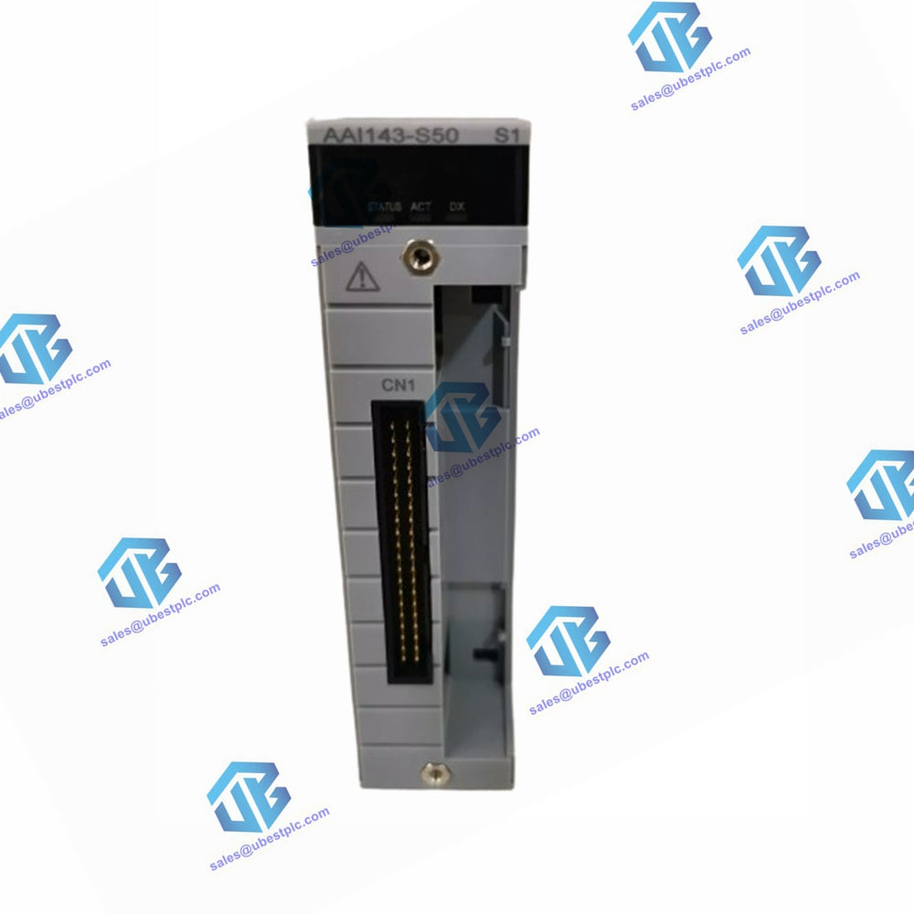
AAI143-S50 | Yokogawa Analog Input Module
UBEST – Trusted Global Automation Parts Supplier
We offer a wide range of in-stock industrial automation spare parts. All products come with a 12-month warranty and a 30-day refund for quality issues.
Current Input Modules (Isolated)
The Yokogawa AAI143-S50 module provides 16 inputs of 4 to 20 mA signals and can be used in dual-redundant configurations.
Items Specifications
Model: AAI143 (*1)
Number of input channels: 16, isolated
Input signal: 4 to 20 mA
Allowable input current: 24 mA
Withstanding voltage:
- Between input and system: 1500 V AC, for 1 minute (*4)
Input resistance:
- Power ON: 270 Ω (20 mA) to 350 Ω (4 mA) (*2)
- Power OFF: 500 kΩ or larger
Accuracy: ±16 µA
Data update period: 10 ms
Transmitter power supply:
- 19.0 V or higher (at 20 mA)
- 25.5 V or less (at 0 mA) (output current limit: 25 mA) (*5)
Setting of 2-wire or 4-wire transmitter: For each channel by setting pin
Drift due to ambient temperature change: ±16 µA/10 ˚C
Maximum current consumption:
- 230 mA (5 V DC)
- 540 mA (24 V DC)
Weight: 0.3 kg
External communication: Pressure clamp terminal, MIL connector cable, dedicated cable (KS1)
HART communication: Available (*3)
Model: AAI143
Description: Analog Input Module (4 to 20 mA, 16-channel, Isolated)
Ordering Number: AAI143-S50
Dimensions (L x W x H): 107.5 mm x 32.8 mm x 130 mm
Suffix Codes
- -S: Standard type
- 5: With no explosion protection
- 0: Basic type
Notes
- A Zener barrier is not allowed to be connected with this module. Use an isolation barrier when the module is used in an intrinsically safe application.
- The module input resistance viewed from the terminals depends on the current strength as calculated as below:
- 250 Ω + current value
- voltage drop in the input protection circuit
- When this module is installed to an ER bus node unit with HART function, the EB401 firmware must be rev. 2 or later.
- When the dedicated cable is used, the withstanding voltage is 500 V AC (between the input signal and the system). When the MIL connector cable is used, the withstanding voltage depends on the electrical specifications of the cable.
- This voltage is generated between the connecting terminals for 2-wire transmitters for this module. When calculating the minimum operating voltage for transmitters, consider allowing margins for voltage drop in external wiring.